Wind Load tab
Used to apply previously created wind load types on the structure through the means of a load case.
Note: If a wind load has not yet been defined for
the model, a warning message is displayed in the dialog and the controls are
inactive. Refer to the
Create Wind Type Definition dialog
to learn more about defining a wind load.
Wind Load tab
Used to add static wind forces per ASCE 7 and other codes.
| Setting | Description | ||||||||
|---|---|---|---|---|---|---|---|---|---|
| Select Type | Choose a previously defined wind load type from the drop down list. | ||||||||
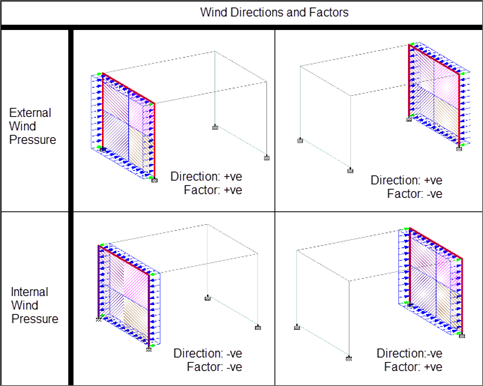
| Direction |
Specify the global direction in which the wind load is to be generated by
selecting the corresponding option:
|
||||||||
| Factor | Specify the factor by which the calculated wind loads will be multiplied. | ||||||||
| Open Structure |
Select this option to generate loads on open structures like highway signs or transmission towers. By default, the load generation is based on the assumption that the region between members is covered by panels (i.e., cladding). Setting this option will apply load to only the members (i.e., no cladding). Tip: The
term used here is not the same as the ASCE 7 definition of
"open structure." Please use the
ASCE 7 Wind Load dialog box
to generate describe the enclosure
classification per this code.
|
||||||||
| SNiP Parameters |
The following parameters are used for wind loads generated per the Russian code (SNiP). Note: Wind loads generated for SP 2.07.7 or SP 20.13330.2016
codes are only available for models with a Y-up orientation.
|
Wind Load - Dynamic tab
Used to specify dynamic wind forces per SP 20.13330.2016.
| Setting | Description |
|---|---|
| Wind Definition | Choose an SP 20.13330.2016 wind load definition from the drop down list. |
| Width of Building along wind dir | Effective length of the structure parallel to wind direction. |
| Wid of Building across wind dir | Effective projection of the structure facing the wind direction. |
| Ground Level | Select if the ground level is not considered (i.e., global Y = 0 is the ground level) or if it is to be specified at different Y coordinate. |
| Factor | Correction factor along specified direction. |
| Internal | Set this option to indicate an internal, or suction, wind force on the surfaces (i.e., the load direction is reversed). |
| Allow all Mode Shapes | Check this option to compute dynamic wind load vector for all mode shapes extracted from Modal Analysis provided it is within code stipulated frequency limit. When this check box is clear, the calculation takes only the first mode shape. |
| Include Orthogonal Load | Check this option to include orthogonal directions in the load case. |
| Static Wind Case | Select a previously defined primary load cases in the model. |
| Wind Direction | Select the plan direction to apply the wind force. |